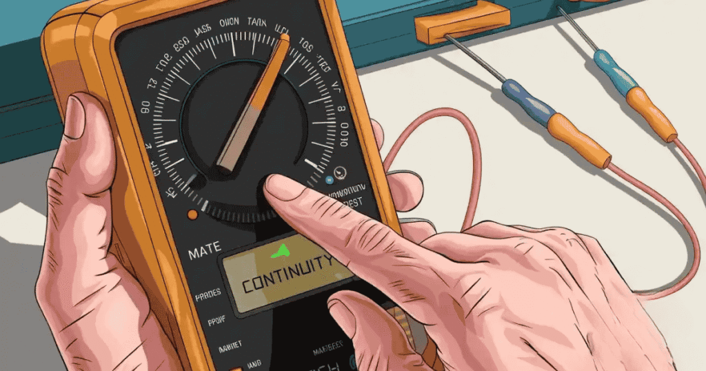

Using a multimeter can feel confusing when you are not sure what each symbol means. You may see a small icon and wonder which setting to choose for testing a wire or connection. The Multimeter Continuity Symbol is useful for checking whether electricity has a complete path. Knowing this symbol can make simple electrical testing much easier and less stressful.
In this guide, you will learn what the Multimeter Continuity Symbol means and where to find it on your meter. You will also learn how continuity mode works and how to use it correctly. Simple testing steps will help you check wires, connections, switches, and circuits with greater confidence while avoiding common mistakes during basic electrical checks.
What Is the Multimeter Continuity Symbol?
The Multimeter Continuity Symbol identifies the setting used to check whether electricity can travel through a circuit. You’ll usually find this symbol near other testing options on a digital multimeter. It may look like curved sound waves, a speaker, or a small buzzer icon. The exact design can vary between different multimeter brands and models.
When you select continuity mode, the multimeter sends a small test current through the circuit. If the circuit has a complete path with low resistance, the meter usually detects continuity. A broken wire, loose connection, or open circuit interrupts that path. The meter may then show an OL reading or another indication of no continuity.
Most digital multimeters provide an audible beep when they detect a suitable connection. This makes testing faster because you don’t need to watch the display constantly. However, not every meter uses the same symbol or sound threshold. Always check your meter’s manual if the continuity setting isn’t clearly marked or looks different from common multimeter symbols.
Why Continuity Testing Is Helpful
Continuity testing helps you quickly check whether an electrical path is complete. It can save time when troubleshooting wires, fuses, switches, and connections. Instead of guessing where a problem exists, you can test the circuit directly with your multimeter and narrow down the faulty area.
It’s especially useful when a circuit suddenly stops working. A quick continuity test can reveal a broken wire, loose connection, or damaged component. The audible beep also makes testing easier because you can focus on the circuit instead of constantly watching the display.
Key benefits include:
- Finds broken wires quickly
- Checks electrical connections
- Helps test fuses and switches
- Supports basic circuit troubleshooting
- Saves time during electrical testing
Where to Find the Continuity Symbol
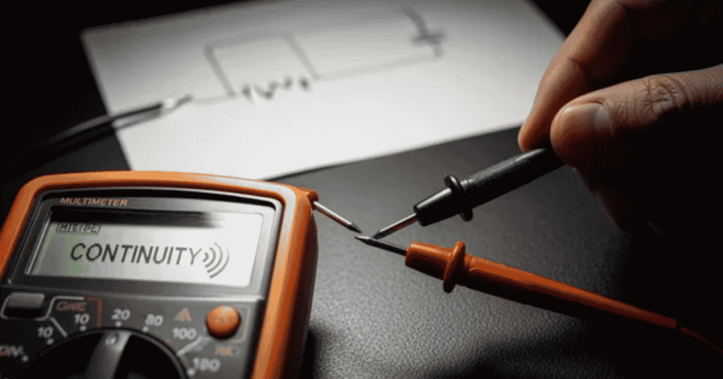
The continuity symbol is usually found on the multimeter’s dial near the resistance and diode settings. Its design may vary between different brands and models.
- Look for a speaker or sound-wave icon.
- Check near the Ω resistance symbol.
- Look beside the diode symbol.
- Some meters combine continuity with diode testing.
- Digital multimeters may show a buzzer icon.
- Check the meter’s display or function buttons.
- Refer to the user manual if you can’t find it.
How Continuity Mode Works
Continuity mode sends a small test current through a wire, component, or circuit. The multimeter checks the resistance along the circuit path. If the path is complete and resistance stays low, the meter detects electrical continuity. This process helps you find good connections, broken wires, and open circuits without measuring the circuit’s normal operating voltage during testing.
When continuity exists, many digital multimeters produce an audible beep to alert you. If the circuit path is broken, the meter may show an OL reading or no beep. The exact beep threshold differs between models. Always switch off power before testing continuity. This protects you, your multimeter, and the electrical components from possible damage.
Read More : BMW Symbol: Meaning, History, Colors, Logo & Evolution
Steps to Use the Multimeter Continuity Symbol
A continuity check can quickly reveal why a circuit isn’t working. You only need the right setting, properly connected leads, and a safe circuit. Think of it like checking whether a road has an open route from one point to another. Follow these simple steps to test connections accurately and avoid common mistakes during basic electrical troubleshooting.
Turn Off Power
Before starting, switch off the circuit’s power and disconnect batteries when possible. Continuity mode sends its own small test current through the circuit, so external voltage can affect readings or damage the meter. For example, never test a powered outlet in continuity mode. Confirm the circuit is de-energized before touching its terminals or placing your multimeter probes on connections.
Select Continuity Mode
Turn the multimeter dial to the continuity setting, usually marked with a speaker, buzzer, or sound-wave symbol. Some models combine continuity with the diode function. If you’re unsure, check the meter’s manual. Select the correct mode before connecting the probes. This prevents confusion between continuity testing, resistance measurements, and other electrical testing functions on the same dial.
Insert the Test Leads
Plug the black test lead into the COM port and the red lead into the appropriate voltage or resistance port. Avoid using a current port for continuity testing. Hold the insulated probe handles while working. Clean, firm contact matters because dirt or loose contact can create unreliable readings. Your multimeter probes should touch the intended points securely.
Test the Meter
Before testing a circuit, touch the two probe tips together. A working meter will usually produce an audible beep and show a very low resistance reading. This quick check confirms that the leads and continuity function are working. If nothing happens, inspect the battery, leads, and selected setting. It’s better to catch a meter problem first.
Test the Circuit
Place one probe on each end of the wire, fuse, switch, or connection you want to check. A beep usually indicates a low-resistance path, while an OL reading commonly indicates an open circuit. For a switch, test it in both positions. This simple comparison can help you locate broken wires, poor connections, or faulty components.
Reading Continuity Test Results
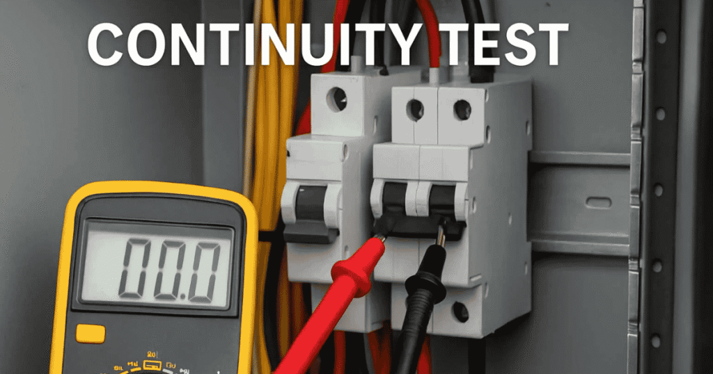
A continuity test shows whether electricity can travel through a complete circuit path. A beep usually means the connection has low resistance and is working. If the meter stays silent, the circuit may be open. Check the display for an OL reading, which commonly means very high resistance or no complete electrical path.
Results can vary between multimeter models, so check your manual when unsure. A low resistance reading usually supports continuity, while a high or OL reading suggests a break. For accurate testing, keep the power off and make firm contact with both test probes. Compare results with the expected circuit condition before replacing any component.
Read More : Blueflamepublishing Blog: Complete Guide to Content, Features & Online Value
Components You Can Test
You can use continuity testing to check many simple electrical components. It helps identify complete paths, broken connections, and faulty parts. Always switch off power before testing any component. The Multimeter Continuity Symbol makes these checks quick and simple. It can help you locate problems without measuring normal circuit voltage during basic electrical troubleshooting tasks at home or work.
Common components and connections you can test include:
- Wires for breaks or damaged sections.
- Fuses for complete electrical paths.
- Switches for proper connections.
- Cables for internal breaks or damage.
- Connectors for secure electrical contact.
- PCB traces for broken paths.
- Relays for continuity across contacts.
Continuity Symbol vs Resistance Symbol
The continuity and resistance settings both check electrical paths, but they serve different purposes. Continuity quickly confirms connections, while resistance measures the exact opposition to current flow.
| Feature | Continuity Symbol | Resistance Symbol |
| Main purpose | Checks whether a circuit path is complete | Measures electrical resistance |
| Common symbol | Speaker, buzzer, or sound-wave icon | Ω symbol |
| Main result | Beep or no beep | Numerical resistance reading |
| Reading | Usually indicates low or high resistance | Shows resistance in ohms |
| Low resistance | Usually triggers a beep | Displays a low Ω value |
| Open circuit | Often shows OL or stays silent | Usually shows OL or very high resistance |
| Testing speed | Faster for quick connection checks | Better for detailed measurements |
| Common uses | Wires, fuses, switches, and connections | Resistors, components, and circuits |
| Audible alert | Many meters produce a beep | Usually no beep |
| Best for beginners | Easy for basic circuit checks | Useful for precise electrical measurements |
Continuity Symbol vs Diode Symbol
The continuity and diode symbols can appear together on some multimeters, but they perform different tests. Continuity checks connections, while diode mode measures diode behavior and forward voltage.
| Feature | Continuity Symbol | Diode Symbol |
| Main purpose | Checks whether an electrical path is complete | Tests diode operation |
| Common symbol | Speaker, buzzer, or sound waves | Triangle-like diode symbol with a line |
| Main result | Beep or no beep | Forward voltage reading |
| Audible alert | Many meters produce a beep | Usually doesn’t rely on a beep |
| Main measurement | Low resistance connection | Diode forward voltage |
| Common use | Testing wires, fuses, and switches | Testing individual diodes and LEDs |
| Open circuit | Usually shows OL or stays silent | Often shows OL when reverse biased |
| Probe placement | Across two points in a circuit | Across the diode terminals |
| Circuit behavior | Looks for a low-resistance path | Checks current flow direction |
| Best for | Quick connection checks | Checking diode condition and polarity |
Common Uses Around the Home
A multimeter can help you check simple electrical problems around your home. Continuity testing is useful for finding broken wires, faulty switches, and poor electrical connections quickly.
- Check extension cords for broken wires.
- Test fuses for electrical continuity.
- Check switches for proper connections.
- Test appliance power cords for breaks.
- Find loose electrical connections.
- Check low-voltage wiring connections.
- Troubleshoot simple circuit problems safely.
Common Uses in Automotive Repair

Continuity testing helps you find electrical problems in vehicles. You can check wires, fuses, switches, connectors, and other circuits when diagnosing starting or lighting problems.
- Check automotive fuses for continuity.
- Test wires for breaks or damage.
- Check switches for proper connections.
- Test battery cables for electrical continuity.
- Check connectors for poor connections.
- Test relay contacts and terminals.
- Troubleshoot lighting circuit problems.
Common Uses in Electronics
Continuity testing is useful when working with electronic circuits. It helps you check connections, PCB traces, wires, switches, and components for breaks or unwanted open circuits.
- Check PCB traces for broken connections.
- Test wires and jumper cables.
- Check switches and buttons.
- Test fuse connections on circuit boards.
- Find loose solder connections.
- Check connectors and terminals.
- Troubleshoot simple electronic circuits.
Safety Tips
Safety should always come first when using a multimeter. Follow basic precautions to prevent electric shock, meter damage, short circuits, and injuries during continuity testing.
- Turn off power before testing continuity.
- Disconnect batteries when possible.
- Never test a live circuit in continuity mode.
- Check test leads for damage.
- Use insulated probe handles.
- Select the correct multimeter setting.
- Keep your fingers away from probe tips.
Common Mistakes
Common mistakes during continuity testing can lead to false readings or damaged equipment. Knowing these errors helps you use the multimeter correctly and get more reliable circuit results.
Before testing, check your meter setting, probe placement, and circuit condition. Small errors can make a good connection appear faulty or create an unsafe testing situation.
The interpretation may vary depending on the situation:
- Testing a live circuit: Continuity mode should only be used on a de-energized circuit. Testing live voltage can damage the multimeter or create a safety hazard.
- Using the wrong setting: Selecting resistance, voltage, or current mode instead of continuity mode can produce confusing results.
- Poor probe contact: Dirty terminals or loose probe contact may prevent the meter from detecting electrical continuity.
- Ignoring the OL reading: An OL reading often indicates an open circuit or very high resistance. Check the connection before assuming a component has failed.
- Skipping the meter test: Touch the probes together first. A beep and low resistance reading can confirm that the continuity function and leads are working properly.
Multimeters That Use the Continuity Symbol
Most digital multimeters include a continuity function for checking electrical connections. The continuity symbol often appears near resistance or diode settings. Different brands may use a speaker, buzzer, or sound-wave icon. Always check your meter’s markings before selecting the continuity mode for accurate testing and safe operation during basic electrical troubleshooting tasks.
Popular multimeter brands commonly provide continuity testing in their digital models. Fluke, Klein Tools, Mastercraft, Ideal, Southwire, and Gardner Bender offer meters with similar functions. The symbol and beep threshold can vary by model. Some meters combine continuity, resistance, and diode testing under one setting, so check the manual when necessary.
Why Beginners Like Continuity Mode
Continuity mode is simple for beginners because it gives a quick answer about electrical connections. The audible beep makes testing easier without watching the multimeter display constantly. It’s useful for basic circuit troubleshooting and helps new users understand how wires, switches, fuses, and other connections work.
Beginners also like continuity testing because the steps are easy to follow. You select the setting, touch the probes to two points, and check the result. A beep usually means a low-resistance path exists. This makes the multimeter continuity symbol a helpful starting point for learning basic electrical testing safely.
Frequently Asked Questions
Here are 12 SEO-friendly FAQs with short, clear answers. Each answer stays within 25–28 words and uses the focus keyword naturally.
What multimeter setting for continuity?
The Multimeter Continuity Symbol marks the continuity setting, usually shown as a speaker, buzzer, or sound-wave icon near resistance and diode functions.
What is a symbol for continuity?
The Multimeter Continuity Symbol commonly looks like a speaker, buzzer, or curved sound waves. It shows the setting used to check complete electrical connections.
What’s a good continuity reading?
A good continuity reading usually shows very low resistance and may produce a beep. The Multimeter Continuity Symbol helps identify this setting quickly.
What does continuity do on a multimeter?
The Multimeter Continuity Symbol activates a test that checks whether electricity can travel through a complete circuit path with low resistance.
Is continuity good or bad?
Continuity is generally good when you expect a complete connection. The Multimeter Continuity Symbol helps confirm that wires, switches, fuses, or connections have a path.
Does 0 ohms mean continuity?
Yes, a reading close to 0 ohms usually indicates continuity. The Multimeter Continuity Symbol commonly produces a beep when the resistance is sufficiently low.
What is a bad continuity reading?
A bad continuity reading often shows OL, very high resistance, or no beep. The Multimeter Continuity Symbol may indicate an open circuit.
How many ohms indicates continuity?
There isn’t one universal resistance value for continuity. Most meters beep below a certain threshold, while the Multimeter Continuity Symbol indicates the selected testing function.
Is 0 ohms a good reading?
Zero ohms or a reading close to zero usually indicates a strong electrical connection. The Multimeter Continuity Symbol can confirm this with an audible beep.
Can I test continuity on a live circuit?
No, don’t test continuity on a live circuit. Always switch off power first before using the Multimeter Continuity Symbol to prevent damage or injury.
Does continuity mean open or closed?
Continuity means the circuit path is closed and allows electrical flow. The Multimeter Continuity Symbol helps check whether two points have a complete connection.
How to read a multimeter?
To read a multimeter, select the correct function, connect the probes, and observe the display. The Multimeter Continuity Symbol usually gives a beep for continuity.
Conclusion
The Multimeter Continuity Symbol makes basic electrical testing simple and fast. It helps you check wires, fuses, switches, connectors, and circuit paths. A beep usually shows a low-resistance connection. An OL reading often points to an open circuit. Always turn off power before testing. Use firm probe contact and select the correct multimeter setting. These simple steps can help you avoid false readings and protect your meter during electrical troubleshooting tasks.
Learning the Multimeter Continuity Symbol is useful for beginners and experienced users. It helps you find broken connections without complicated testing. You can use continuity mode around the home, in automotive repair, and when working with electronics. However, continuity testing should never replace proper safety procedures. Always check your multimeter manual because symbols, beep thresholds, and readings can vary between models. With regular practice, continuity testing becomes easier, quicker, and more reliable.